page 1
Introduction
What are ley lines?
Ley lines were the ‘discovery’ of a Herefordshire businessman named Alfred Watkins back in 1921. In his book The Old Straight Track, he wrote: “My main theme is the alignment across miles of country of a great number of objects, or sites of objects, of prehistoric antiquity. And this not in one or a few instances, but in scores and hundreds.”
Ley lines, then, are the alignments, stretching over the countryside, of tumuli and barrows, camps and forts, moats and earthworks, trackways and old churches (often built over old pagan sites). Alignments sometimes many miles long, crossing each other in great profusion like some intricate street plan of a super city.
But ley lines or simply ‘leys’ were relatively quickly forgotten. The archaeologists muttered about ‘chance effects’ and ‘mares’ nests’, and the convinced ley hunters continued to hunt their leys in spite of the scientists.
It was the 1960s which revived ley hunting, only with one or two added twists. Whereas Watkins had believed the alignments to be simple trackways, the ley line revival brought with it esoteric significance. Ley lines were the pathways of some subtle natural energy, harnessed by ancient man for religious purposes and magical practices. Ghosts and elementals were said to be active in the region of these lines, and some said that flying saucers were observed to fly along them.
In 1958, Aimé Michel had put forward orthoteny – his theory that UFO sightings were strung out in vast straight lines. It was only a matter of time before someone linked the similar concepts of leys and orthoteny, and in the early sixties a curious booklet by J.A.D. (Tony) Wedd came forward to foot the bill.
Not surprisingly, orthoteny suffered the same scientific derision that leys had earlier in the century. Were the alignments involved in either system anything but simple effects of chance? Were they both, in fact, similar phases of the same linear dream?
As far as orthoteny was concerned, Jacques and Janine Vallée hurled a rather large spanner into the works in 1967 in their book Challenge to Science – the UFO Enigma (pp. 76 ff.), but as far as I know, no serious investigation on an orthodox scientific basis has ever been published to attempt to refute ley lines.
In order that the case against ley lines be made intelligible to the average reader, I present only basic results in the text, the derivation of formulae and other more technical details being reserved for appendices. However, it is necessary that the reader bear with one or two details to begin with in order to appreciate points of importance.
Acknowledgements
I would like to thank Mr C.P. Robinson for his help in the computing involved in the determination of the various values of the mean length of a ley; and Mr C.P. Mallett for his help in the computing involved in the tables of the Furness formula, and also the evaluation of Q(at least one>r) in Appendix 3A.
page 2
Introduction to the problem of chance alignments

Fig. 1.
Imagine two dots, P and Q, placed on a rectangular sheet of paper. The two dots are joined and the line produced until it hits the edges of the paper at A and B (see Fig. 1). If a third dot, R, is put on the paper completely at random, what is the likelihood that it will fall somewhere on the line PQ? If the dots are made as small as possible and if the line is drawn with a sharp pencil, the answer is ‘very, very unlikely’.
But the situation for the ley hunter poring over his maps, and searching for alignments of ancient monuments, is not quite so simple.

Fig. 2.
Corresponding to the dots P and Q we now have, let us say, two earthworks or
churches which, on the map, are not dots but small areas, and whereas there is
only one line which can be drawn to join two dots, there are clearly many lines
which can be drawn to join two areas – see Fig. 2. Further, we are no
longer placing a third dot on the map but a third area, R, and the condition
that it should align with P and Q is now that some line joining
P and Q, possibly produced, should pass through some part of R.
Fig. 3 shows some possible outcomes.

Fig. 3. (a) R can fall ‘spot on’ PQ, as at R2, or can fall slightly either side, and yet still be in alignment.
(b) Both lines 1 and 2 ‘join’ PQ, yet R lies on only one of them.
The scope for producing chance alignments in the case of ley hunting is thus greater than that for dots and thin lines, for the simple reason that our notion of what constitutes an alignment has loosened considerably in passing from dots to areas – see Fig. 4.

Fig. 4. (a) Tight alignment. (b) Looser alignment.
How are we to describe the conditions for such alignments mathematically? To simplify matters, we begin by supposing that our ley points* are circles of diameter x. We choose two of them, P and Q, and seek the probability that other ley points, assumed to have been scattered over the map at random, will link up on some alignment of P and Q. That is can we place a ruler over the map in some position such that its edge passes through both P and Q, and through at least one other point on the map?
* The term ‘ley point’ is used under the emphasis that the word ‘point’ is, strictly speaking, a misnomer.

Fig. 5. R1 has its centre a distance d > x/2 from the dotted line and is not in alignment with P and Q.
R2 has d < x/2, however, and so is in alignment with P and Q.
Referring to Fig. 5, P and Q define a corridor of width x, whose central axis is the dotted line, and a third ley point, R, can be counted to align with P and Q if its centre lies within a distance x/2 either side of the dotted centre line. The probability, p, that this will happen is easily evaluated, being simply the area of the corridor (xL) divided by the total area of the map, A. We write:
|
(1) |

Fig. 6.
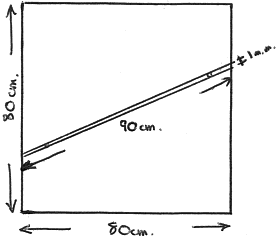
Applying this, the new series of 1:50,000 OS maps are 80 cm by 80 cm. If our ley points have a width of 1 mm or 0.1 cm, and if the corridor in question is 90 cm long, the probability that a third ley point will fall in alignment is given very nearly by:
|
or just over 1 in 1000, a probability which looks deceptively small, and yet which is mammoth compared with the corresponding probability for the simple dot alignments with which we began our discussion. It is also a large enough probability, as will be seen shortly, for alignments to start happening to quite a startling degree, even with relatively few points on the map.

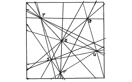
Fig. 7. As few as 6 points (P, Q, R, S, T, U) can be used to define many corridors or lines.
The fact is that though the probability of alignment for a particular corridor PQ is small, the map may contain hundreds of ley points which can be used to define literally thousands of corridors like PQ (see Fig. 7 for a simple example). For example, from 200 ley points, P and Q can be selected to define no less than 19,900 corridors, and by sheer force of numbers, small probability or otherwise, some of these are going to produce alignments of 3, 4, or even 5 or more points. Looked at in another way, the chance of getting a simple 3-point alignment may only be 1 in 1000 at any given attempt, but with 19,900 attempts at our disposal, we are highly likely to succeed more than once.
page 3
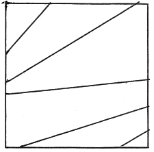
However, the above is a rather simplified version of what goes on, in that the same value of p does not apply to all corridors. To see why this is so, return for a moment to equation (1). Different corridors have different lengths, L, and so even though x and A remain constant, the value of p will vary from corridor to corridor (see Fig. 8).

Fig. 8. The lengths of the corridors shown are all different.
The values of p for each corridor are therefore also different.
What we would like then is an average value for p, and to obtain this we require an average value for L. It is fairly easy to see that the average value of L is simply the average width of the map in question.
At this point, the help of a computer was enlisted. Details of the procedure used are given in Appendix 5, and the end results only stated here:
- The average width of a square 1 unit by 1 unit is 1.08 units.
- The average width of a rectangle 1 unit by 1.5 units is 1.34 units.
- The average width of a rectangle 1 unit by 2 units is 1.61 units.
2014: For more precise values and a theoretical discussion, see the update to Appendix 5
Thus, for a map representing an area 25 miles by 25 miles, the average corridor length, and thus the average length of a ley line, is 25×1.08=27 miles nearly, a result used in Appendix 1.
Once the average value of L is known, the average value of p can be found by equation (1). And once p is known it becomes mathematically possible to determine approximately how many 3-point, 4-point, 5-point etc. leys one can expect to find on a given map containing any number of specified points. Details are to be found in Appendix 1.
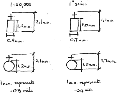
A word on the value of x in equation (1). In practice, of course, ley points are not all circular and not all the same size, as we assumed for the purposes of the above discussion. For this reason, an average corridor width, x, must be sought for particular cases of ley lines under consideration. The symbols for church with tower and church with spire, for example, have an average width (on both old 1-inch and new 1:50,000 maps) representing about 0.03 mile. An alignment of type Fig. 4(a) might, because of its tightness of fit, entail an x value of only 0.01 mile, whereas that of type Fig. 4(b) would use the full corridor width of 0.03 mile. Most published leys fall between the two types, with an average x value of about 0.02 mile, though occasionally, for example with moat alignments, a larger x value is entailed (see also Fig. 9).

Fig. 9.
Also, some ley ‘points’ have a considerable area on the map – e.g. Old Sarum, Maiden Castle – and alignments involving such ‘points’ would entail such a large corridor width as to nullify the concept of alignment for smaller ley points. I propose, therefore, to make allowance for such points and will refer to them as ‘large points’. Thus, a ley of order 8 which includes two large points will be treated as a ley of order 6 for purposes of comparison with the chance hypothesis.

Fig. 10. Leys tend to skirt large points rather than pass through their centres.
It is of interest that ley hunters (e.g. Screeton p. 40; Tyler p. 25) have noted that leys tend to skirt the edges of large points, rather than pass through their centres (see Fig. 10). This effect is also seen to be a property of the chance effect hypothesis – see Graph 1.
One final word, and that concerns a basic assumption of the chance hypothesis. In all the calculations that follow, ley points are assumed to have a uniform random distribution over the whole map. This is not the case in practice as, for example, churches tend to cluster about towns, and tumuli to gather in groups on higher ground – to a degree of clustering which is not a feature of a pure chance model.
However, the chance model is useful in that it does give some idea of the almost unexpected frequencies of chance alignments to be expected amongst a stated number of random points, and comparison with the ley lines ‘discovered’ by ley hunters on maps is certainly instructive, and, to my mind at least, a rather damning case against ley lines. It shows at the very least that the caprice of randomness is not to be underestimated.