This document decribes how to set up a basic RMS Gateway using LinBPQ - the Linux version of the BPQ32 Networking package. Although the instructions are slanted toward using a Raspberry PI, which because of the combination of small size and low price and power consumption makes a good choice for a gateway, the software can run on other Linux systems. Familiarity with the Winlink 2000 system is assumed, along with a (very) basic Linux knowledge.
Although there are other ways of providing a Packet RMS
Gateway (eg
LinuxRMS) LinBPQ has the advantage of supporting a range of Data over
Radio protocols (eg Pactor, Robust Packet, WINMOR) as well as ax.25
Packet, allowing it to provide much the same facilites as RMS Trimode.
Note that although WINMOR is supported, until a Linux port of the
WINMOR TNC is produced, a separate Windows machine is required to run
the TNC. LinBPQ can also run a store and forward system which can
provide similar facilites to RMS Relay, and Winlink Client facilites
similar to Paclink.
BPQ32/LinBPQ is a pretty complex package, with many options.
This
document describes how to set up a simple, single protocol gateway
without having to wade throuugh a lot of irrelevant stuff. Once you
have a basic system running if you want to add other options it
shouldn't seem so
complicated. If you want more information, the full specification of
bpq32.cfg is here
.
If you are using a Raspberry Pi and are completely new to the PI, there are intructions on
how to do the basic setup of the Pi Linux operating system here. Stop when you get to the "Installing LinBPQ section and continue here.
I've written a simple script to download, install and configure LinBPQ as a Winlink RMS Gateway. The script
can be seen here, and the configuration file bpq32.cfg it installs here
Download the script using wget, set it as executable and run it:
wget http://www.cantab.net/users/john.wiseman/Downloads/installLinRMS
chmod +x installLinRMS
./installLinRMS
This will create the directory linbpq and download linbpq and other needed files into it. It will prompt for your callsign and edit bpq32.cfg with your call.
LinBPQ configuration is held in file bpq32.cfg. LinBPQ refers to links to the outside world as PORTS. These may be radio links, paths over the Internet, or wire links. For an RMS Gateway you need at least two - one to connect to the CMS over the Internet, and one for your users to connect to over radio. The management interface is Web based and uses the same port as CMS Access. A bpq32.cfg file with a Telnet port for management and connecting to a CMS is installed as by the above installation script. You will need to edit to add your Winlink PASSWORD. Replace CMSPASS with your RMS Gateway password, and user and password in the USER line with something suitable. You can change HTTPPORT, TCPPORT and FBBPORT to other values if they clash with ports you are using for other software. If you set LOCATOR to your Grid Square, the software will send you position to the BPQ32 Node Map.
Various options for radio ports are described below.
At this point if you wish you can start the software, and check that the CMS connection works using the Web Management Interface.
cd linbpq
./linbpq
You should see something like
pi@pi6 ~/linbpq $ ./linbpq
G8BPQ AX25 Packet Switch System Version 6.0.17.2 November 2018
Copyright © 2001-2018 John Wiseman G8BPQ
Current Directory is /home/pi/webmail/linbpq

Configuration file Preprocessor.
Using Configuration file /home/pi/webmail/linbpq/bpq32.cfg
Conversion (probably) successful

PORTS 1e67a8 LINKS 1e7544 DESTS 1ea444 ROUTES 1f09d4 L4 1f23d4 BUFFERS 1f87f0

Initialising Port 01     Telnet Server
Note that LinBPQ is intended to run in the background, (see later for how to set this up) so you can't interact with it, except to shut it down withctrl/c
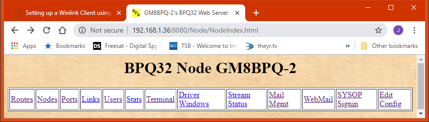
Open a Web browser, either on the LinBPQ machine or another on the same network and connect to 127.0.0.1:8080 if using a local browser or ipaddr:8080 if using a remote machine. You should see the node management page:
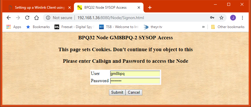
If you are connecting to 127.0.0.1 you will be logged into the management interface automatically. If not, you need to sign in using the SYSOP Signin link. If you haven't edited the USER line the user and password are "user" and "password"
Click on the Teminal Tab, end enter RMS to connect to the Winlink Server. You should see someting like
Trying ec2-52-205-46-246.compute-1.amazonaws.com
*** GM8BPQ Connected to CMS
[WL2K-5.0-B2FWIHJM$]
;PQ: 94918477
CMS via GM8BPQ >
Type B to close your session to the CMS and click "Close and Return to Node" to end your terminal session.
If this is ok, you can go on and configure your radio port(s).
All radio ports include a WL2KREPORT line, which sets up reporting to the Winlink channels database. Edit this line with the infomation for your station. Fields are
Service, Host, Port, Callsign, Locator, Hours, Freq, Mode, Power, Ant Height, Ant Gain, Ant Direction
See
here for more information on reporting to the WL2K staton
database.
Using TNC-Pi
The TNCPi
is a version
of the TNC-X KISS TNC modified to be the same size as the PI and to
connect to it via either its serial port or i2c bus. If you
use
i2c you can connect more than one TNC, but for simplicity this example
uses the serial port. See here
for
instructions on using i2c.
PORT
 ID=1200 Baud 144.xxx
 TYPE=ASYNC
 PROTOCOL=KISS
 CHANNEL=A
 COMPORT=/dev/serial0
 SPEED=19200 ; Must by 19200 for TNC-Pi
 MAXFRAME=4
 FRACK=8000
 RESPTIME=1500
 RETRIES=10
 PACLEN=128
 KISSOPTIONS=PITNC,NOPARAMS

 WL2KREPORT PUBLIC, www.winlink.org, 8778, MYCALL-10, XXnnXX, 00-23, 144800000, PKT1200, 10, 20, 5, 0

ENDPORT
Using other
types of KISS TNC
Normally TNC's will be connected to the pi using USB, and will appear as device /dev/ttyUSB0.
PORT
 ID=1200 Baud 144.xxx
 TYPE=ASYNC
 PROTOCOL=KISS
 CHANNEL=A
 COMPORT=/dev/ttyUSB0
 SPEED=9600 ; Change as required
 MAXFRAME=4
 FRACK=8000
 RESPTIME=1500
 RETRIES=10
 PACLEN=120
 TXDELAY=300
 SLOTTIME=100
 PERSIST=64

 WL2KREPORT PUBLIC, www.winlink.org, 8778, MYCALL-10, XXnnXX, 00-23, 144800000, PKT1200, 10, 20, 5, 0

ENDPORT
Copy your bpq32.cfg after the Telnet Port config, and if necessary change parameters to suit you local packet network.
Robust Packet is a protocol developed by SCS using standard ax.25 frames, but with a modulation method similar to Pactor II. It generally is considered to be more effective on HF than normal 300 baud FSK Packet. It normally runs at 600 baud, but can fall back to 300 on poor channels. It is supported by the SCS Tracker and some PTC models. It would be arather a waste to use a PTC just for Robust Packet, but it can also be ocmbined with Pactor - see the Pactor section for details
SCS Tracker.
The Tracker connects to the Pi using USB, and appears as
/dev/ttyUSB0. Note that early PI kernels would crash when trying to
access the tracker, so make sure your Kernel is up to date (at least
Version 3.6.11+ Build 393)..
PORT
 ID=Tracker
 DRIVER=SCSTracker
 COMPORT=/dev/ttyUSB0
 SPEED=38400 ; COM Port Speed
 PORTCALL=MYCALL-10

 CONFIG ; Driver-Specific Configuration

 APPL RMS ; Autoconnect to BPQ32 RMS Application

 USEAPPLCALLS ; Listen for calls to any of your APPLnCALLS
 DEFAULT ROBUST ; Return to Robust mode after connections

 WL2KREPORT PUBLIC, www.winlink.org, 8778, MYCALL-10, XXnnXX, 00-23, 14103000, ROBUST, 10, 20, 5, 0

ENDPORT
Change MYCALL to your callsign
Most stations use one o the SCS range of comtrollers for Pactor, as these are the only ones that support Pactor II and above. However LinBPQ also supports AEA KAM and HAL controllers.
SCS Pactor
Cotrollers.
Any of the SCS Pactor controllers can be used. These will normally connect via USB, ether via a USB-Serial converter or a built-in USB Port. You can also use the PI's built in serial port, but this would need a TTL (3.3V) to RS322 converter.
If you have a PTC PRO with Packet modules, these can be used on packet at the same time as the main port is used on Pactor.
If you have a non-PRO module you can use either Pactor or Robust Packet. The software can be set to scan between the two. This is decribed later in the section on scanning.
PORT
 ID=Pactor Link
 DRIVER=SCSPactor
 COMPORT=/dev/ttyUSB0
 SPEED=38400 ; COM Port Speed

 CONFIG ; Driver-Specific Configuration

 APPL RMS ; Autoconnect to CMS

 PSKA 140 ; PSK TX Output level.
 FSKA 100 ; TX Level for FSK modes

 WL2KREPORT PUBLIC, www.winlink.org, 8778, MYCALL-10, XXnnXX, 00-23, 14103000, P123, 10, 20, 5, 0

ENDPORT
Alter PSKA and FSKA as requited. if you are using a Dragon,
add the
following line before ENDPORT. To comply with US regulations, the
Dragon will be limited to P3. If your administration permits P4, also
add MAXLEVEL=4
DRAGON
If you wish to use any packet ports on a PTC PRO, you will
need to
set suitable ax.25 params, for example:
 PACKETCHANNELS 10 ; Enable Packet Ports

 PAC TXD 1:250
 PAC TXD 2:200

 WL2KREPORT PUBLIC, www.winlink.org, 8778, MYCALL-10, XXnnXX, 00-23, 145000000, PKT1200, 10, 20, 5, 0
 WL2KREPORT PUBLIC, www.winlink.org, 8778, MYCALL-10, XXnnXX, 00-23, 433000000, PKT9600, 10, 20, 5, 0
These also go before ENDPORT
Scanning is supported for most ICOM and Kenwood rigs with a CAT interface. Some Yeasu rigs are also supported, but as Yeasu dont have a standard, not all work.
Scanning is controlled by the RIGCONTROL configuration statement, which goes before ENDPORT. A example configuration is
RIGCONTROL
 COM6 9600 ICOM IC718 5E
 5,3.5855,USB,F1,P23,W1
 5,7.1,USB,F1,P23,W1
 5,14.103,USB,F1,P123,W2
****

Each Frequency/Mode entry consists of a comma separated list with the following format:

 Dwell Time (Time before changing frequncy in seconds, decimals allowed, resolution 100ms)
 Frequency (Mhz)
 Mode (can normally be abbreviated to first char, but handles modes such as PKT-L, FSK-R, PKT-FM.
 One or more options, separated by commas. Options are:
 A1-A4 - Antenna Switching via DTR/RTS
 F1-F3 - IF Filter for ICOM Rigs
 H1 H2 - HF Packet 300 or 1200 (SCS Tracker only)
 P1 P12 P123 P1234 P2 P23 P234 P3 P34 P4 - Pactor Modes.
 R1 R2 - Robust Packet 300 or 600 (SCS Tracker only)
 W1 W2 - WINMOR 500 or 1600 (WN and WW are also accepted)
 X - Don't Report to WL2K
 + - S - Repeater Shift/Simplex (only on ICOM rigs)
 D - Set Data Mode on IC746
See http://www.cantab.net/users/john.wiseman/Documents/RigControl.html for a full specification
When you have configured you redio port, close and restart
LinBPQ,
and you should now be able to connect to
MYCALL-10 from your preferred WL2K client and send/receive message from
the CMS.