Introduction
The National Grid reference system was introduced in Britain shortly after the Second World War. A single map projection (Transverse Mercator) covers the whole of Great Britain, replacing the old system in which each county, or group of counties, had its own projection. Knowing the grid references of two points anywhere in Britian, it is therefore easy to find the distance and bearing of one from the other.
When studying the possibility of long-distance prehistoric surveying, one ought to allow for distortions in the map projection caused by the curvature of the Earth. Such distortions are small, but are just enough to matter. The formulae in these notes should enable points to be located to within 1 part in 2 000 000, e.g. to within 0.5 metre for a line extending the whole length of Britain.
Coordinate system
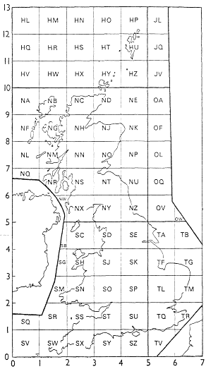
The Ordnance Survey divides the country into squares of side 100 km. Each square is identified by a pair of letters, as shown in the diagram. Within each square, the easting and northing are indicated decimally, with the number of figures depending on the accuracy required. The easting is always written first.
Example: the centre of the tower on Glastonbury Tor has grid reference
| ST 512 386 | (to the nearest 100 m) |
| ST 5122 3862 | (to the nearest 10 m) |
| ST 51219 38616 | (to the nearest 1 m) |
For calculations the grid coordinates must be expressed wholly in figures. The method in these notes is to use a unit of 100 km to express the easting (E) and northing (N) of a point. In this way:
- The figures after the decimal point are just the same as the figures in the conventional grid reference;
- The figures before the decimal point correspond to the letters in the conventional grid reference, according to the diagram.
Example: Centre of the tower on Glastonbury Tor, ST 51219 38616.
E = 3.51219, N = 1.38616 (correct to 5 decimals or 1 metre).
Example: Ben Nevis triangulation station, NN 1668 7128.
E = 2.1668, N = 7.7128 (correct to 4 decimals or 10 metres).
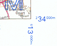
The figures before the decimal point here are the same as those that appear in small type at the corners of Ordnance Survey maps. For example, the map corner shown on the right has coordinates
| E = 6.13, N = 2.34 |
Notation
In the formulae below, P1 and P2 are two points in Britain.
P1 has easting E1 and northing N1, and P2 has easting E2 and northing N2, in 100-km units as above.
The formulae also use quantities D1 and D2, defined by
| D1 = E1 − 4, D2 = E2 − 4. |
PD = plane distance: the distance from P1 to P2, calculated from the coordinates without correcting for map distortion.
PA = plane azimuth: the azimuth from P1 to P2, calculated from the coordinates without correcting for map distortion.
GD = geodesic distance: the distance on the ground from P1 to P2, found from PD by correcting for map distortion.
GA = geodesic azimuth: the azimuth on the ground from P1 to P2, found from PA by correcting for map distortion.
NB: Both PA and GA are measured clockwise from grid north. Calculating the difference between grid north
and true north is a separate problem (see section on Convergence below).
Distance
To find the distance between P1 and P2, first apply Pythagoras’ Theorem to get the plane distance:
| PD = √[(E2 − E1)2 + (N2 − N1)2]. |
To find the geodesic distance GD, i.e. the actual distance on the ground, use the correction
| GD / PD = 1.00039889 − 0.00004092(D12 + D1D2 + D22) | (1) |
Azimuth
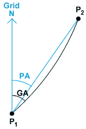
Suppose we want the azimuth (measured clockwise from grid north) of the line from P1 to P2. The plane azimuth PA, i.e. without allowing for distortion, is found by applying simple trigonometry.
The geodesic line joining P1 to P2 on the ground will not usually appear as an exactly straight line on the map. To find the geodesic azimuth GA of the line at P1, use the correction
| GA − PA = 0.002345(2D1 + D2)(N2 − N1) degrees. | (2) |
Note: The map projection used by the Ordnance Survey does not distort angles. Hence the angle on the ground between two lines will be exactly equal to the difference between their geodesic azimuths at the crossing point.
Reverse problem
This problem here is to find the grid coordinates of P2, given the geodesic distance GD and geodesic azimuth GA from a known point P1. The appropriate formulae are
| E2 = E1 + (PD)sin(PA) | (3) |
| N2 = N1 + (PD)cos(PA) |
but initially the plane distance PA and plane azimuth PA are not known. Therefore, obtain a first approximation to E2 and N2 from (3), assuming that the plane values are the same as the geodesic values. The resulting values of E2, N2, and D2 (= E2 − 4) are accurate enough to use in formulae (1) and (2), which will give the PD and PA. By applying (3) a second time the correct values of E2 and N2 can now be found.
Example of reverse problem
Taking the initial point P1 to be Glastonbury Tor (E1 = 3.51219, N1 = 1.38616), find the point P2 that is 195 km distant on grid azimuth 243°.
Here GD = 1.95, GA = 243°. Get a first approximation from (3) by assuming PD = GD and PA = GA:
| E2 = 3.51219 + 1.95sin(243°) = 1.77473 |
| N2 = 1.38616 + 1.95cos(243°) = 0.50088 |
Now D1 = 3.51219 − 4 = −0.48781, and D2 = 1.77473 − 4 = −2.22527, so by formulae (1) and (2) above:
| GD / PD = 1.00014210, GA − PA = 0.00664° |
whence
| PD = 1.95 / 1.00014210 = 1.9497229, PA = 243° − 0.00664° = 242.99336° |
giving as the final result
| E2 = 3.51219 + 1.9497229sin(242.99336°) = 1.77508 |
| N2 = 1.38616 + 1.9497229cos(242.99336°) = 0.50080 |
Convergence
The difference between grid north and true north can amount to 4° or more. The true azimuth of grid north is known as the convergence. If it is required (e.g. for astronomical purposes) to know the azimuth of a line measured from true north rather than grid north, we need to calculate the geodesic azimuth (GA above) and then add the convergence. The convergence can be estimated from the data on O.S. maps, or else calculated from the grid coordinates. In the formulae below, P is a point in Britain; E and N are the easting and northing of P in 100-km units; D = E − 4.
Quick formula
Convergence at P = D(1.0652 + 0.0318N+ 0.0010N2) degrees (maximum error = 0.007°).
Accurate formula
Calculate A = 49.7865 + 0.89873N degrees, then calculate B = 0.734 D secA degrees.
Convergence at P = 0.900594 D tanA cosB degrees (maximum error = 0.00004°).
Spherical excess
If a polygon with n sides is drawn on a plane, the sum of the angles is (180n − 360)°, e.g. 180° for a triangle. If a polygon is drawn on a sphere, the sum of the angles is greater than this. The difference is called the spherical excess and is proportional to the area of the polygon.
With a unit of 100 km as above, the spherical excess in a polygon laid out in the landscape and having a surface of area A square units is
| 0.014067 A degrees. |
Example
In landscape geometry, suppose an equilateral triangle has side 195 km; find the angle at each vertex. The area is
| (√3/4)1.952 = 1.64653 square units, |
whence the spherical excess is 0.02316°, so that each angle of the triangle is 60.00772°. As noted above, the map projection used by the O.S. does not distort angles, so the sides of the triangle will meet at this angle on the map as well as on the ground.
Astronomy
To find the declination (δ) of an astronomical object, given the true azimuth (α), true altitude (h) after allowing for refraction and parallax, and the north latitude (φ) of the place of observation:
| sinδ = cosα cosh cosφ + sinh sinφ |
To find the true azimuth from the other quantities:
| cosα = sinδ sech secφ − tanh tanφ |